Functional Neurosurgery · DBS Planning
Planning the Core DBS Targets
STN, GPi, and Vim from starting coordinates to patient-specific anatomy
A practical review of how standard DBS coordinates are converted into anatomically constrained targets, trajectories, and verification strategies for movement-disorder surgery.
Orientation
DBS planning begins with a coordinate, but the coordinate is not the target. A starting point is a hypothesis placed into a stereotactic coordinate system; the final target is an anatomical and physiological decision constrained by the individual AC-PC geometry, the visible nuclei and fiber corridors, the planned trajectory, and the expected therapeutic field.
The convention used here lists coordinates as lateral / anteroposterior / vertical relative to the midcommissural point, with negative values posterior and inferior. Laterality is displayed as ± to denote mirrored right and left targets. The default seeds are STN ±12 / -3 / -4, GPi ±22 / +2 / -4, and Vim ±14 mm from midline / 25% anterior to PC / 0. For Vim, the commonly cited 10-11 mm value refers to distance lateral to the third-ventricle wall, not distance from midline.
The central planning habit is therefore iterative: set the seed, interrogate the anatomy, modify the seed only for a reason, draw a trajectory that respects the target across several millimeters of depth, and document why the chosen plan is superior to plausible alternatives.
STN
±12 / -3 / -4
The seed is refined on T2 or susceptibility-weighted anatomy toward the posterolateral sensorimotor STN and the STN-zona incerta border, using the red nucleus and medial STN border as the most reliable visual anchors.
GPi
±22 / +2 / -4
The seed is refined toward posteroventral motor GPi. The plan must account for the optic tract inferiorly, internal capsule medially and posteriorly, GPe laterally, and the desired contact span through the ventral pallidum.
Vim
±14 mm ML / 25% anterior to PC / 0
The seed is indirect because the Vim nucleus is not discretely visualized on routine MRI. The lateral coordinate is reconciled with a 10-11 mm offset from the third-ventricle wall, third-ventricle width, thalamic atrophy, Vc posteriorly, internal capsule laterally, and the expected course of the dentato-rubro-thalamic tract.
The Planning Frame
1.The Coordinate Is a Seed
A coordinate is useful because it creates a disciplined first look. It places the cursor close enough to the intended structure that the rest of the plan can become anatomical. Its danger is that it can conceal the patient-specific relationships that matter most: commissural length, third ventricular width, red nucleus morphology, STN iron conspicuity, pallidal shape, cortical entry constraints, and the expected direction of lead deviation.
The AC and PC should be identified on a high-quality volumetric T1 sequence using the commissural convention built into the planning system. In this workflow, the AC-PC line follows the Talairach tangential convention derived from ventriculographic stereotaxy: the superior intraventricular border of the anterior commissure and the inferior border of the posterior commissure are selected, rather than the geometric center of each commissure. The AC-PC line defines the intercommissural plane, and the midcommissural point defines the coordinate origin. An AC-PC distance in the usual adult range supports the standard atlas assumptions; a markedly long or short distance should prompt scrutiny of landmark selection, image distortion, and whether percentage-based anterior-posterior coordinates are more reliable than fixed millimeter values.
2.Image Set and Registration
Planning should be performed on volumetric, no-gap imaging. The minimal practical stack is a stereotactic CT or frame-localized acquisition, a high-resolution T1 sequence for AC-PC and vessels, and target-specific MRI. Our practice is to order an FGATIR MRI sequence for every DBS case, so pallidal, thalamic, and subthalamic anatomy can be reviewed consistently even when the final target is primarily defined on another sequence. T2-weighted imaging remains central for STN planning because it shows the red nucleus and iron-rich STN. FLAIR, MPRAGE, and susceptibility-sensitive sequences may further improve pallidal and subthalamic definition. Diffusion imaging is optional for many STN and GPi cases but increasingly important for tremor planning, where the dentato-rubro-thalamic tract is often a better patient-specific object than the invisible Vim nucleus.
Registration error should be treated as a biological problem, not a software inconvenience. The target is small, the therapeutic window is measured in millimeters, and even a visually acceptable fusion can be wrong in the region of interest. Fusion should be checked at the cortical entry zone, ventricles, skull base, AC-PC region, red nuclei, basal ganglia borders, and the planned target slice. If postoperative CT or intraoperative imaging will be used for verification, the preoperative protocol should already anticipate how lead artifacts will be interpreted.
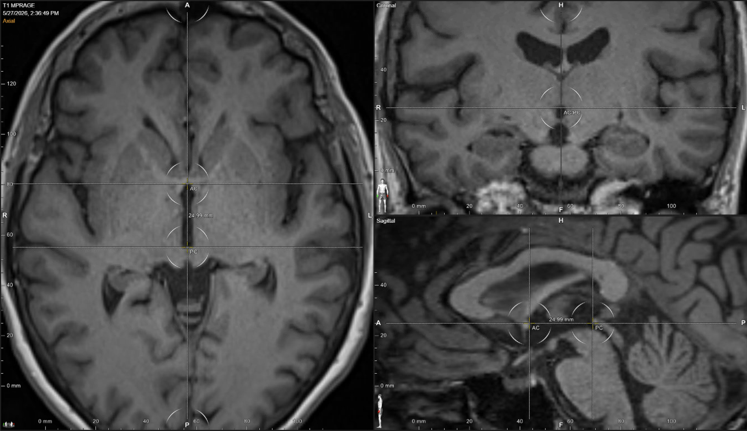
Figure 1.AC-PC coordinate setup and stereotactic origin. The sagittal panel defines AC and PC using the Talairach tangential convention; the axial panel confirms the intercommissural plane and paired superior-collicular appearance; the coronal panel confirms midline alignment.
3.Trajectory Before Target Approval
Target approval should not occur before the trajectory has been drawn. A point that is anatomically attractive may be unusable if the path crosses a sulcus, cortical or deep vessel, ventricle, caudate head, eloquent cortex, or a narrow cisternal/ependymal corridor likely to deflect the electrode. The preferred entry is usually near the coronal suture, through a gyral crown and white matter, with enough obliquity to sample the target but not so much that the electrode skims tissue planes or loses useful contact coverage.
For STN and Vim-region plans, a relatively steep trajectory close to the coronal suture often gives a favorable compromise between safety and target coverage. For GPi, the trajectory is less forgiving: a lateral target, the optic tract below, and the internal capsule along the posteromedial border leave little room for a casual angle. The plan must be evaluated along the entire implanted contact array, not only at the tip.
| Target | Seed | Primary confirmation | Critical boundary | Planning pressure |
|---|---|---|---|---|
| STN | ±12 / -3 / -4 | T2-visible red nucleus and medial/posterior STN, sensorimotor dorsolateral STN, STN-ZI border | Internal capsule lateral/anterior, medial lemniscus posterior, oculomotor territory medial/deep, SNr inferior | Optimize several millimeters of lead through motor STN and adjacent white matter rather than centering the nucleus |
| GPi | ±22 / +2 / -4 | Posteroventral motor GPi, pallidocapsular border, GPe-GPi lamina, optic tract depth | Optic tract inferior, internal capsule medial/posterior, GPe lateral, putamen lateral/anterior | Preserve contact span in ventral GPi and avoid an apparently acceptable point reached by a poor pallidal trajectory |
| Vim | ±14 mm ML or 10-11 mm from third-ventricle wall / 25% anterior to PC / 0 | Atlas/AC-PC construction, third-ventricle wall offset, Vc border, internal capsule, thalamic width, DRTT or PSA relationship when available | Vc posterior, internal capsule lateral/ventral, speech/gait circuitry with bilateral stimulation | Recognize that the therapeutic object may be a cerebellothalamic fiber bundle rather than a sharply visible thalamic nucleus |
Planning STN
4.The Target Is Posterolateral Sensorimotor STN
The STN seed ±12 / -3 / -4 falls within the usual atlas window for Parkinson disease, but the final plan should be built from the red nucleus and STN rather than from the atlas. The clinical target is the posterolateral sensorimotor STN and its dorsal border with the zona incerta. This is why a lead that appears to pass through the center of the nucleus is not automatically better than one that captures the dorsolateral border and adjacent white matter.
The STN is best approached on the T2 sequence after the AC-PC line has been established on T1. At the chosen axial level, the image window should be narrowed until the red nucleus separates cleanly from the hypointense STN. If a small anterior red-nucleus protrusion is visible, the line should follow the overall anterior contour of the red nucleus rather than being pulled anteriorly by that projection. The posterior STN tip and medial border are more important than the lateral border, which is frequently indistinct. In older patients or patients with lower iron conspicuity, the posterior tail may seem truncated; the anterior-medial STN and red nucleus usually remain usable anchors.
- Place the seed at ±12 / -3 / -4 and confirm the side-specific AC-PC orientation.
- Select the axial level near the maximum diameter of the red nucleus, commonly around 3.5-4.5 mm below AC-PC, and optimize the T2 window for the red nucleus-STN interface.
- Draw a Bejjani-style line along the smoothed anterior red nucleus border, adjusted for head rotation or tilt.
- Set the anterior-posterior position on that line or slightly posterior to it, depending on the visible STN relationship.
- Identify the medial STN border at that level and move approximately 1.5-2 mm lateral into the nucleus.
- Draw the trajectory and inspect the electrode path through superior STN on successive axial and coronal levels above the target.
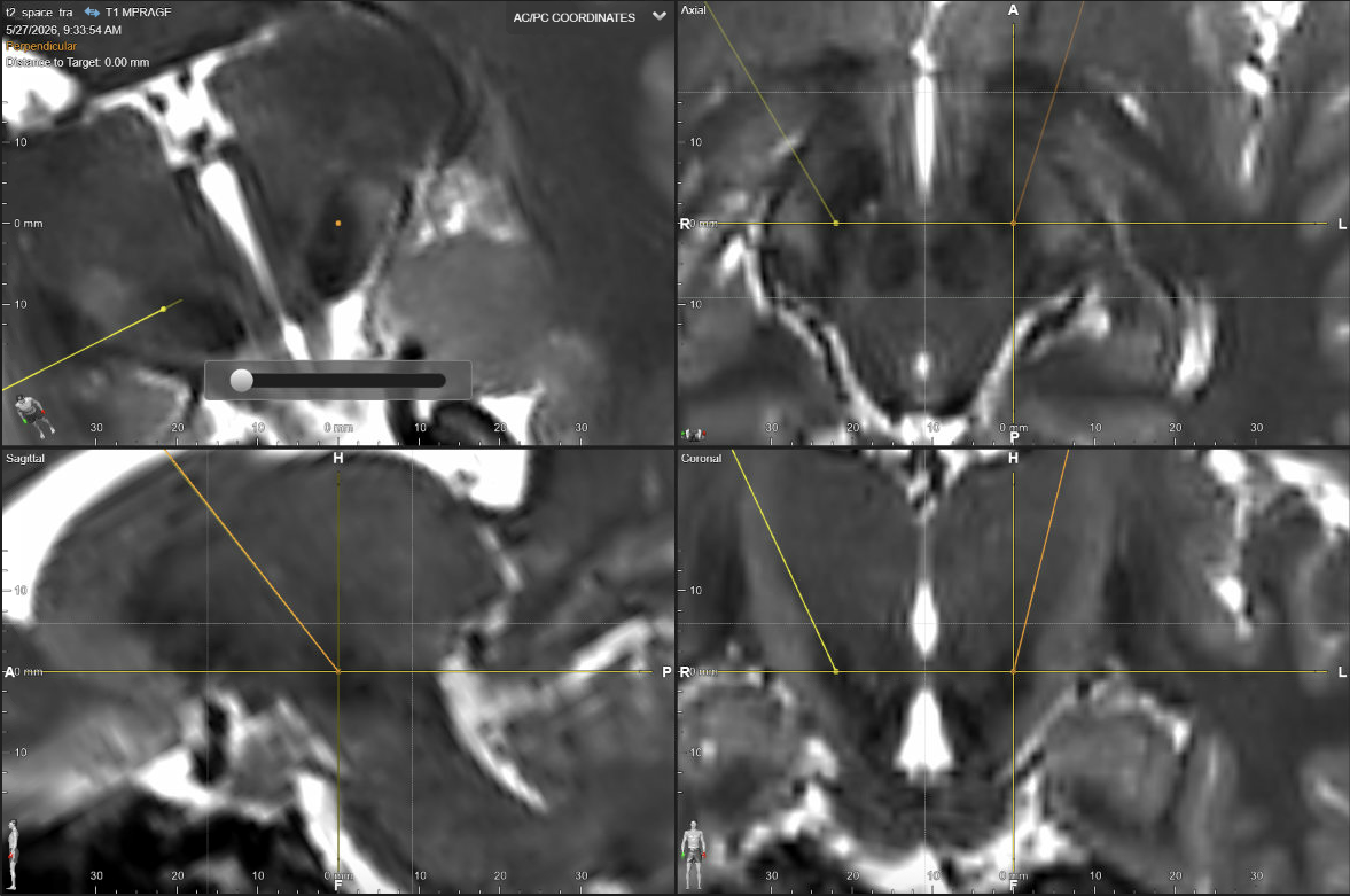
Figure 2.STN trajectory and orthogonal target review. Probe-eye, axial, sagittal, and coronal views confirm the planned lead path through the subthalamic target region.
5.STN Lead Geometry and Side-Effect Logic
The final lead should make anatomical sense across the contact array. The distal contact should not be deliberately placed in the substantia nigra pars reticulata, although the deepest portion of the array may approach the ventral STN/SNr boundary depending on lead model and institutional practice. More dorsal contacts should give access to the dorsolateral STN and the STN-ZI transition, where many effective chronic fields are ultimately programmed.
Side-effect thresholds are a localization tool. Face or arm contraction implies capsular spread, especially lateral or anterior to the target. Paresthesia suggests posterior spread toward medial lemniscus or sensory thalamic pathways. Monocular oculomotor deviation implies excessive medial/deep stimulation, while conjugate deviation points toward corticobulbar/corticonuclear fiber activation. Mood change with deep stimulation should raise concern for ventral spread toward SNr or nonmotor territory. These signs should be interpreted with imaging and lead reconstruction rather than as isolated anecdotes.
Planning GPi
6.The Target Is Posteroventral Motor GPi
The GPi seed ±22 / +2 / -4 is close to the classic pallidal target range, but GPi is the least forgiving of the three targets discussed here. The reason is anatomical: the useful motor territory is a posteroventral portion of a curved structure, bordered by the optic tract inferiorly, internal capsule posteromedially, GPe laterally, and putamen laterally and anteriorly. A lead can be close in Euclidean distance and still fail if the trajectory samples the wrong pallidal compartment.
Planning begins by identifying the GPi on the best available pallidal sequence, often FGATIR, FLAIR, or high-quality T1/T2 fusion depending on local protocol. The working axial level is usually the AC-PC plane or approximately +1 mm above it, because the GPi is often broad and well delineated there. This rule should not override the scan: if the nucleus has its clearest borders and typical shape at -1 mm, that level can be used after confirming on adjacent slices that the appearance is not a partial-volume illusion, registration artifact, or misread GPe/putamen boundary.
The direct targeting task is geometric. Define the visible GPi, identify the internal medullary lamina and pallidocapsular border, then deliberately divide the posterior GPi into thirds. The target is placed within the posterior third, usually near its center but biased slightly anterolateral rather than hugging the posteromedial capsule. The medial and lateral borders of that posterior third should be defined on the chosen slice before accepting the X and Y coordinate. This is the step that converts ±22 / +2 / -4 from a number into a patient-specific target.
Adjacent levels then decide whether the chosen point is truly usable. The posteromedial GPe can flare posteriorly and make the pallidal outline look deceptively generous; the plan should therefore be checked above and below the selected slice for continuity of GPi, GPe, putamen, lamina, capsule, and optic tract. A target that is ideal on one axial image but leaves the contact array in GPe, capsule, or optic-tract-adjacent tissue is not a good GPi plan. The accepted point is often a compromise that keeps the middle contacts in posteroventral motor GPi while preserving a safe ventral margin.
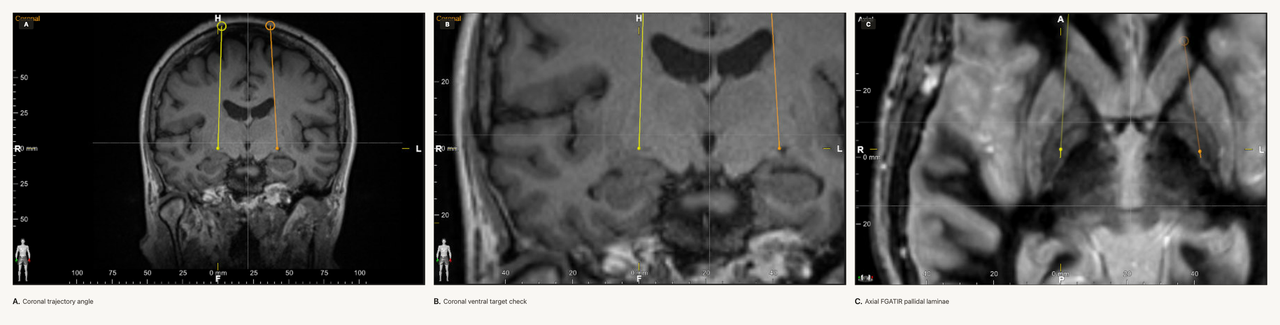
Figure 3.GPi trajectory, optic-tract relationship, and pallidal laminae. The panels connect coronal lead angle, ventral target position, and axial FGATIR anatomy.
7.Depth, Contact Span, and the Optic Tract
GPi depth is not merely a coordinate. The deepest contact should sit just superior to the optic tract or at the ventral GPi margin, depending on lead geometry and the intended indication. Too shallow a plan risks chronic stimulation in GPe or dorsal GPi, with weak therapeutic effect. Too deep a plan narrows the therapeutic window through visual phenomena and nonmotor spread. Too medial or posterior a plan quickly becomes capsular.
Physiology, when used, should confirm the anatomical hypothesis: striatum is relatively sparse and low frequency; GPe often has pauser and burster activity; the GPe-GPi transition may include border cells; GPi is dense, irregular, high frequency activity; the optic tract is silent but may respond to visual stimulation or microstimulation with phosphenes. The planned trajectory should explain these expected transitions before the first pass is made.
- Place the seed at ±22 / +2 / -4 and verify that the intended target is posteroventral motor GPi, not simply lateral basal ganglia.
- Scroll through the axial pallidal sequence and select the level where GPi is largest and most believable, usually AC-PC or +1 mm, occasionally -1 mm if the adjacent slices support it.
- Define GPi, GPe, putamen, the internal medullary lamina, and the pallidocapsular border. Be skeptical of posteromedial GPe expansion that can mimic a larger posterior GPi.
- Measure the posterior GPi and define its posterior third, including its medial and lateral borders, before moving the target in X or Y.
- Place the target within the posterior third, near the center of that compartment but slightly anterolateral to the most posteromedial border.
- Inspect coronal and sagittal planes for the ventral pallidal contour, the expected optic tract boundary, and whether the selected point gives a coherent lead axis rather than a single good axial dot.
- Confirm that the middle contacts will sample posteroventral motor GPi, the deepest contact will not be driven into the optic tract, and the highest contact being in or near GPe is acceptable rather than surprising.
Planning Vim
8.The Target Is a Tremor Network Node
The Vim seed is an indirect thalamic construction. A practical midline seed is ±14 mm / 25% anterior to PC / 0, while the traditional 10-11 mm lateral value should be understood as an offset from the wall of the third ventricle. Unlike STN and GPi, Vim is not reliably segmented on routine structural MRI. The target is therefore defined by the AC-PC line, the posterior commissure, the third ventricle, the expected anterior border of Vc, the internal capsule, and, when available, diffusion tractography of the dentato-rubro-thalamic tract.
Classical coordinates place Vim in the lateral thalamus, anterior to the PC by roughly one-fifth to one-quarter of AC-PC length, near the AC-PC plane, with laterality adjusted for third ventricular width. In practice, the lateral coordinate is checked in both coordinate languages: approximately 14-15 mm from midline, and approximately 10-11 mm lateral to the third-ventricle wall. Brain atrophy, third-ventricle enlargement, thalamic width, and distance from the internal capsule determine whether the final coordinate should sit closer to the lower or upper end of that range. The hand region is typically targeted just anterior to Vc. A slightly anterior position reduces sensory side effects; a more posterior position may improve tremor capture but narrows the paresthesia threshold. Lateral or ventral spread reaches internal capsule and can produce dysarthria or contractions.
Modern tremor planning should also consider that many effective Vim fields intersect cerebellothalamic fibers in or near the posterior subthalamic area rather than only the thalamic nucleus. Contemporary tractography and tremor-targeting literature supports the dentato-rubro-thalamic tract, and the region between posterior STN and red nucleus, as a common therapeutic pathway for tremor. This does not make classical Vim obsolete; it reframes Vim planning as part of a vertical tremor-network trajectory.
If a combined Vim-PSA/cZI strategy is chosen, the lower target should be planned anatomically from the red nucleus and posterior STN rather than from a fixed subthalamic coordinate. The target is first considered on the axial level where the red nucleus has its largest diameter. At that level, the mid-red-nucleus line, the lateral red-nucleus border, and the posteromedial/posterior STN boundary define the working corridor. A practical target lies between the red nucleus and STN, usually in the lateral third of that corridor, with the final point adjusted to preserve distance from capsule laterally and from Vc/medial lemniscus posteriorly. The tentative lower target is then extended cranially through the Vim region: if the resulting path cannot provide both useful thalamic coverage and a reasonable safe entry, the entry point and lower target are adjusted iteratively rather than forcing either target in isolation.
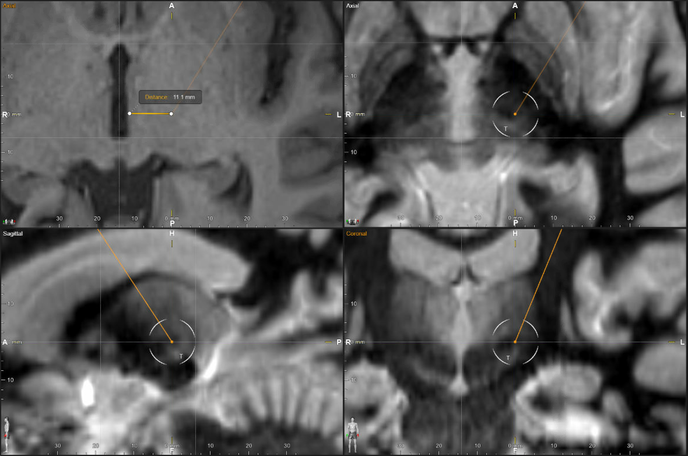
Figure 4.Vim indirect laterality and FGATIR trajectory check. The montage combines third-ventricle-wall lateral measurement with orthogonal FGATIR trajectory confirmation.
9.Vim Trajectory and the Subthalamic Option
The Vim trajectory should preserve useful programming levels rather than placing all effective tissue at one contact. An overly steep anterior-posterior angle can limit contact choices for side-effect avoidance; an overly shallow approach may reduce the number of contacts with tremor benefit. The path should avoid sulci and ventricles and should be reviewed for whether the same lead can reasonably sample both Vim and the posterior subthalamic/cZI region if that is part of the strategy. In a combined plan, the lower contacts should interrogate the PSA/cZI corridor while the upper contacts remain useful for thalamic stimulation.
When a combined Vim-PSA/cZI trajectory is anatomically feasible, it may offer a broader programming corridor for tremor. When it is not feasible, the plan should not blindly force the atlas Vim point at the expense of a safer or more anatomically persuasive tremor-fiber trajectory. The decision depends on tremor phenomenology, imaging quality, tractography confidence, laterality, speech and gait risk, and the institution’s experience with thalamic versus subthalamic tremor targets.
- Construct the AC-PC based seed at approximately ±14 mm from midline, 25% anterior to PC, and 0 mm vertical.
- Reconcile the lateral coordinate with the ventricle-based convention, aiming roughly 10-11 mm lateral to the third-ventricle wall while accounting for atrophy, third-ventricle size, thalamic width, and distance from the internal capsule.
- Estimate the Vc border and place the therapeutic thalamic target just anterior to the expected hand sensory region.
- Overlay DRTT tractography when available and judge whether the planned field intersects the cerebellothalamic pathway.
- If planning PSA/cZI coverage, move to the axial level where the red nucleus has its largest diameter and identify the mid-red-nucleus line, lateral red-nucleus border, and posteromedial/posterior STN boundary.
- Place the lower target anatomically between the red nucleus and posterior STN, usually in the lateral third of that corridor, rather than treating a fixed coordinate as the starting point.
- Extend the tentative target cranially through Vim and review whether one trajectory can offer thalamic and subthalamic tremor contacts without compromising capsule, Vc, medial lemniscus, cortical entry, or ventricular avoidance.
- Adjust the entry point and lower target slightly as needed so that both the Vim-region and PSA/cZI portions of the plan remain safe and therapeutically useful.
Verification and Audit
10.Physiology, Stimulation, and Image Confirmation
Verification should answer a preoperative question rather than serve as ritual. In awake MER-guided STN planning, the expected passage includes sparse zona incerta, a sharp increase in STN background activity, motor-responsive units in the sensorimotor region, and a ventral transition toward SNr. In GPi, the passage should distinguish striatum, GPe, laminar/border activity, dense GPi, and the optic tract region. In Vim, physiology and macrostimulation may identify tremor cells, kinesthetic responses, and the Vc transition from motor to sensory responsiveness.
Asleep image-guided surgery shifts the burden from real-time physiology to the quality of image acquisition, registration, instrument accuracy, intraoperative imaging, and postoperative reconstruction. The two approaches are not opposites; both require a clear definition of the intended anatomical target and a plan for what will trigger revision, re-pass, or acceptance. A lead should not be accepted simply because the planned number appears correct, and it should not be rejected solely because a coordinate differs from the original seed.
11.Stimulation Side Effects as a Map
Test stimulation is most useful when every side effect is interpreted as a spatial clue. The first question is not simply whether a side effect occurred, but at what threshold it appeared relative to benefit. A high-threshold, transient paresthesia may be acceptable during programming. A low-threshold capsular contraction before clinical benefit is a different problem: the therapeutic window is too narrow, and the field is probably too close to the wrong structure.
The troubleshooting sequence should be systematic. Reproduce the effect, record the amplitude and pulse width, decide whether it is transient or sustained, then reduce current density before declaring the lead misplaced. Common programming moves include lowering amplitude, shortening pulse width, changing to a different contact, steering current away from the implicated structure, using a bipolar montage, or using asymmetric bilateral settings. During intraoperative testing, a reproducible low-threshold side effect with poor benefit may justify a directional correction of the lead, but only after the anatomy, trajectory, and imaging registration have been rechecked.
| Target | Side effect during stimulation | Likely structure | Localization clue | Troubleshooting move |
|---|---|---|---|---|
| STN | Face or arm pulling, tonic contraction, low-threshold dysarthria | Internal capsule or cerebral peduncle | Field is too lateral, anterior, or broad for the intended motor STN window. | Lower amplitude or pulse width; steer medial/posterior; try a more posterior, medial, or dorsal contact. If intraoperative and benefit is poor, consider a posterior or medial correction based on imaging. |
| Paresthesia | Medial lemniscus or posterior sensory fibers | Field is too posterior for the intended STN field. | Reduce current density; steer or move anterior; avoid posterior-facing segments if directionality is available. | |
| Conjugate gaze deviation | Corticobulbar/frontal-eye-field fibers near capsule or cerebral peduncle | Usually implies excessive lateral spread. | Steer medial, reduce amplitude, or select a more medial contact. During intraoperative testing, persistent low-threshold effect supports a medial correction. | |
| Diplopia, disconjugate gaze, or monocular eye deviation | Oculomotor nerve or fascicles | Field is too medial, ventral, or deep. | Move stimulation dorsal/lateral; avoid ventral contacts; shorten pulse width. If intraoperative, consider lateral and/or dorsal correction. | |
| Fear, panic, emotionality, hypomania, or depressive affect | Limbic STN, substantia nigra, medial forebrain bundle region | Field is too ventral, medial, or nonmotor. | Reduce amplitude; choose a dorsal/posterolateral contact; steer away from ventromedial tissue. During testing, a dorsal correction is favored when the effect is reproducible at low threshold. | |
| Dyskinesia at low amplitude | Sensorimotor STN or adjacent motor fibers | Often indicates target engagement rather than malposition, especially when transient. | Ramp gradually, lower amplitude or pulse width, and coordinate medication reduction. Persistent troublesome dyskinesia may require a more dorsal contact or narrower field. | |
| GPi | Face pulling, arm contraction, increased tone, capsular dysarthria | Posterior limb of internal capsule | Field is too medial/posterior or too large for the pallidal therapeutic window. | Lower amplitude or pulse width; steer lateral/anterior; test adjacent contacts. If intraoperative and thresholds are poor, reassess whether the lead is too medial/posterior. |
| Flashing lights or phosphenes | Optic tract | Field is too ventral or the lead is too deep relative to ventral GPi. | Use a more dorsal contact, reduce amplitude, shorten pulse width, or move the lead dorsally if encountered intraoperatively at low threshold. | |
| Poor motor benefit without side effects at high settings | GPe, putamen, or nonmotor/dorsal pallidum rather than posteroventral GPi | The field is safe but may not intersect the motor GPi sufficiently. | Review reconstruction; test more ventral/posterior contacts; consider whether the trajectory, not only the coordinate, missed motor GPi. | |
| Vim / PSA | Numbness or paresthesia | Ventral caudal nucleus or medial lemniscus, depending on depth | Field is too posterior or too deep/posterior relative to the Vim/DRTT corridor. | Reduce amplitude or pulse width; steer anterior; try a more anterior or dorsal contact. Transient sensory symptoms may habituate, but persistent low-threshold paresthesia narrows the window. |
| Dysarthria, mouth pulling, or capsular speech effect | Internal capsule or corticobulbar fibers; sometimes bilateral field summation | Field is too lateral/ventral or bilateral current is excessive. | Steer medial, reduce amplitude or pulse width, use bipolar shaping, and check the combined bilateral setting rather than each side in isolation. | |
| Ataxia, dysmetria, gait imbalance, or delayed incoordination | Cerebellothalamic fibers, DRTT, or posterior subthalamic area overactivation | The tremor network is engaged, but the field is too intense, too posterior/inferior, or too bilateral. | Lower amplitude, shorten pulse width, consider lower frequency, move to a more dorsal/anterior contact, or use asymmetric settings when bilateral stimulation is necessary. | |
| No tremor benefit and no side effect | Insufficient capture of Vim/DRTT/PSA tremor pathway | The field may be safe but off-network. | Test adjacent contacts along the vertical trajectory, review DRTT/PSA relationship, and consider whether the active field should move ventral/posterior toward the tremor fiber corridor. |
12.The Final Planning Audit
Before the plan is signed, each side should be audited in a fixed sequence. First, confirm the image set and fusion quality. Second, confirm AC-PC and coordinate convention. Third, confirm the target-specific anatomy on axial, coronal, and sagittal views. Fourth, inspect the entire trajectory from skin to target for vessels, sulci, ventricles, caudate, and cortical entry. Fifth, inspect the entire contact array, not only the tip. Sixth, document the expected side-effect boundaries and the planned method of verification.
This audit is especially important for bilateral cases. Pneumocephalus, CSF loss, frame or robot mechanics, registration differences, and sequence distortion do not affect every side identically. The second side should be planned with the same rigor as the first, while recognizing that intraoperative brain shift may not be linearly correctable from the first-side result.
- STN, GPi, and Vim planning should start from standard coordinates but end with patient-specific anatomy.
- Use ±12 / -3 / -4 for STN as a seed, then target posterolateral sensorimotor STN and the STN-ZI border.
- Use ±22 / +2 / -4 for GPi as a seed, then directly define the posterior third of GPi at the best pallidal level, usually AC-PC or +1 mm, before accepting the X/Y position.
- Use approximately ±14 mm from midline / 25% anterior to PC / 0 for Vim as a seed, then reconcile with a 10-11 mm third-ventricle-wall offset, Vc, capsule, and DRTT.
- STN and Vim-region targets are often more forgiving for tremor than GPi; GPi demands stricter trajectory discipline.
- Lead geometry matters as much as the terminal coordinate because chronic programming uses contacts and fields, not a mathematical point.
- Side effects are localization data: capsule, lemniscus/Vc, optic tract, oculomotor region, and nonmotor STN territory each have recognizable signatures.
- Troubleshooting begins with current density and contact selection before assuming the lead is wrong.
- A complete plan specifies the seed, the anatomical modification, the entry, the trajectory, the expected contact locations, and the verification strategy.
Selected References
- Talairach J, Tournoux P. Co-planar stereotaxic atlas of the human brain: 3-dimensional proportional system: an approach to cerebral imaging. Stuttgart/New York: Thieme; 1988. WorldCat
- Rughani A, Schwalb JM, Sidiropoulos C, et al. Congress of Neurological Surgeons systematic review and evidence-based guideline on STN and GPi DBS for Parkinson disease: executive summary. Neurosurgery. 2018;82(6):753-756. PubMed
- Hirabayashi H, Tengvar M, Hariz MI. Stereotactic imaging of the pallidal target. Mov Disord. 2002;17 Suppl 3:S130-S134. PubMed
- Nowacki A, Fiechter M, Fichtner J, et al. Using MDEFT MRI sequences to target the GPi in DBS surgery. PLoS One. 2015;10(9):e0137868. PMC
- Akram H, Sotiropoulos SN, Jbabdi S, et al. Subthalamic deep brain stimulation sweet spots and hyperdirect cortical connectivity in Parkinson disease. NeuroImage. 2017;158:332-345. UCL Discovery
- Dembek TA, Roediger J, Horn A, et al. Probabilistic sweet spots predict motor outcome for deep brain stimulation in Parkinson disease. Ann Neurol. 2019;86(4):527-538. PubMed
- Iorio-Morin C, Fomenko A, Kalia SK. Deep-brain stimulation for essential tremor and other tremor syndromes: a narrative review of current targets and clinical outcomes. Brain Sci. 2020;10(12):925. PubMed
- Gravbrot N, Saranathan M, Pouratian N, Kasoff WS. Advanced imaging and direct targeting of the motor thalamus and dentato-rubro-thalamic tract for tremor: a systematic review. Stereotact Funct Neurosurg. 2020;98(4):220-240. PubMed
- Kübler D, Kroneberg D, Al-Fatly B, et al. Determining an efficient deep brain stimulation target in essential tremor: cohort study and review of the literature. Parkinsonism Relat Disord. 2021;89:54-62. PubMed
- Middlebrooks EH, Okromelidze L, Carter RE, et al. Directed stimulation of the dentato-rubro-thalamic tract for deep brain stimulation in essential tremor: a blinded clinical trial. Neuroradiol J. 2022;35(2):203-212. PMC
- Coenen VA, Sajonz B, Prokop T, et al. The dentato-rubro-thalamic tract as the potential common DBS target for tremor of various origin: an observational case series. Acta Neurochir. 2020;162:1053-1066. Springer
- Sugiyama J, Toda H. A single DBS-lead to stimulate the thalamus and subthalamus: two-story targets for tremor disorders. Front Hum Neurosci. 2022;16:790942. Frontiers
- Koeglsperger T, Palleis C, Hell F, Mehrkens JH, Bötzel K. Deep brain stimulation programming for movement disorders: current concepts and evidence-based strategies. Front Neurol. 2019;10:410. Frontiers
- Merola A, Romagnolo A, Krishna V, et al. Current directions in deep brain stimulation for Parkinson disease: directing current to maximize clinical benefit. Neurol Ther. 2020;9(1):25-41. PubMed
- Martinez-Nunez AE, Sarmento FP, Chandra V, et al. Management of essential tremor deep brain stimulation-induced side effects. Front Hum Neurosci. 2024;18:1353150. PubMed
- Kim MJ, Chang KW, Park SH, Chang WS, Jung HH, Chang JW. Stimulation-induced side effects of DBS in the Vim and posterior subthalamic area for essential tremor. Front Neurol. 2021;12:678592. Frontiers